25

2025

-

06

What are the functions of the 8 pins of an RJ45 connector?

Author:


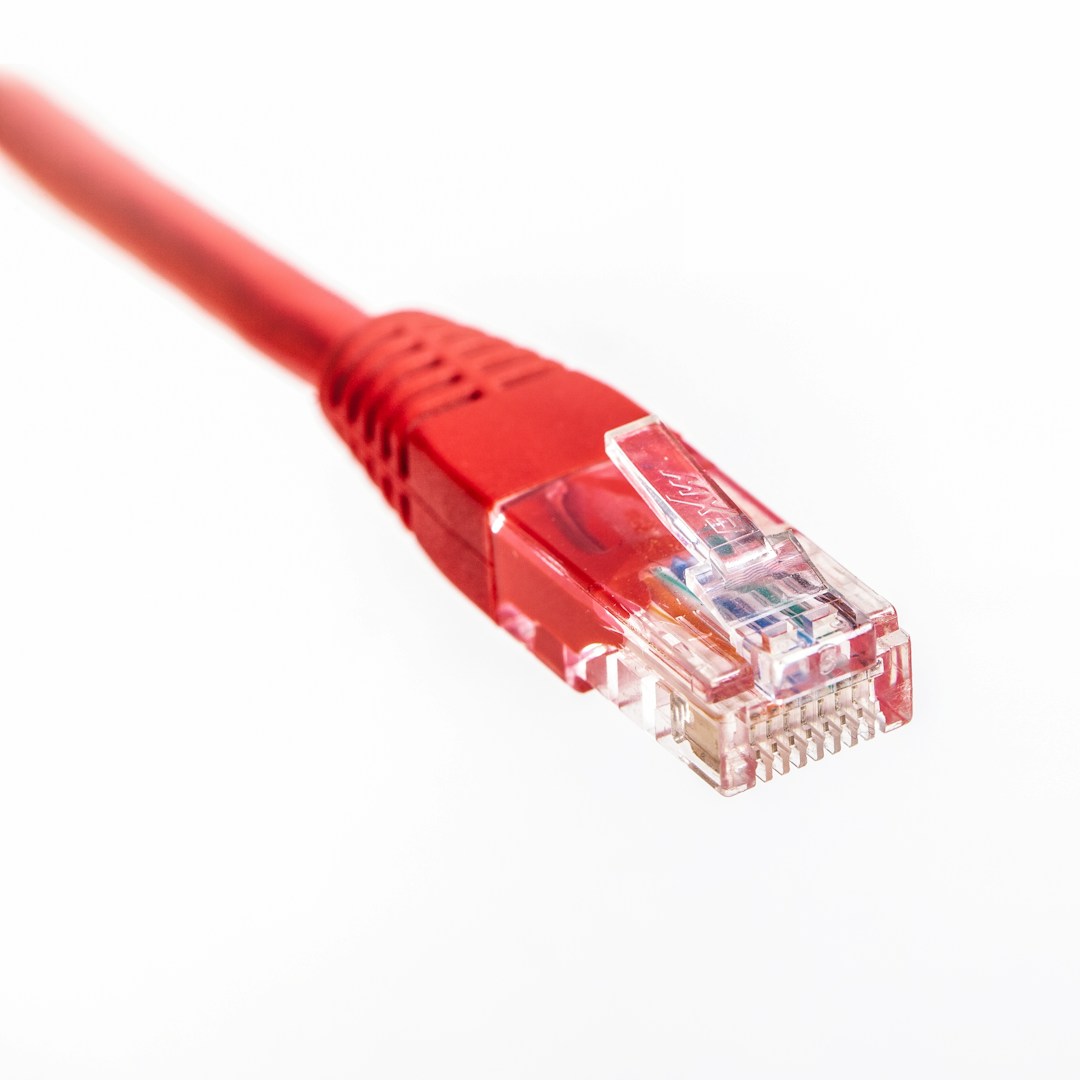
The eight pins of an RJ45 connector serve different functions in Ethernet transmission, including signal transmission and power supply. Their definitions follow the IEEE Ethernet standard. A detailed explanation is provided below:


I. Pin Numbering and Standard Wiring

The pin numbers of an RJ45 connector are arranged from left to right (with the metal contacts facing up and the connector end facing you), corresponding to the T568B standard wiring (most commonly used) as follows:
Pin Number Color Function Category
1 White-Orange Transmit Data Positive (TX+)
2 Orange Transmit Data Negative (TX-)
3 White-Green Receive Data Positive (RX+)
4 Blue Spare / Ground
5 White-Blue Spare / Ground
6 Green Receive Data Negative (RX-)
7 White-Brown Spare / Ground
8 Brown Spare / Ground


II. Pin Functions at Different Network Speeds


1. 10BASE-T/100BASE-TX (100Mbps Network)

  • Data Transmission Pins: Only 4 wires are used (1/2/3/6)
    • 1/2: Form the transmit differential pair (TX+/-), used for device data transmission;
    • 3/6: Form the receive differential pair (RX+/-), used for device data reception;
  • Spare Pins: 4/5/7/8 are usually grounded or unused. In some cases, they are used to connect telephone lines (e.g., VoIP devices).


2. 1000BASE-T (Gigabit Network)

  • Full-duplex transmission: Uses all 8 wires (4 pairs of differential signals)
    • 1/2: Transmit differential pair 1 (TX1+/-);
    • 3/6: Receive differential pair 1 (RX1+/-);
    • 4/5: Transmit/Receive differential pair 2 (TX2/RX2+/-);
    • 7/8: Transmit/Receive differential pair 3 (TX3/RX3+/-);
  • Note: In Gigabit networks, each pair of pins simultaneously handles transmission and reception, achieving bidirectional transmission through full-duplex technology.


3. PoE (Power over Ethernet) Scenarios

  • 802.3af/at standard (PoE+):
    • Power Pins: Power is transmitted through 4/5 (positive) and 7/8 (negative), or 1/2/3/6 simultaneously transmits data and power (pin allocation varies depending on the power supply mode);
    • For example: Mode A uses 1/2 (+) and 3/6 (-), Mode B uses 4/5 (+) and 7/8 (-). Wiring needs to be based on the PoE type supported by the device.


III. Comparison of Pin Functions between T568A and T568B

Standard Pins 1-2 Pins 3-6 Application Scenarios
T568A White-Green / Green (RX+/-) White-Orange / Orange (TX+/-) Crossover Cable (Direct Device Connection)
T568B White-Orange / Orange (TX+/-) White-Green / Green (RX+/-) Straight-Through Cable (Device - Switch/Router)
Core Difference The transmit/receive pins of T568A and T568B are reversed. Therefore, crossover cables need to reverse the wiring order of pins 1-2 and 3-6, used for direct computer connections, etc., while straight-through cables follow a unified standard (usually T568B).


IV. Engineering Application Points for Pin Functions

Signal Integrity:
  • Differential pairs (such as 1/2, 3/6) should maintain a twisted state to reduce electromagnetic interference (EMI). Unused pins are recommended to be grounded;
  • In Gigabit networks, the twist pitch of the four twisted pairs needs to match the cable type (e.g., CAT6a requires a twist pitch ≤0.5mm).
 
PoE Power Supply Precautions:
  • Confirm the PoE mode (A/B) supported by the device to avoid reverse connection causing device damage;
  • The 802.3at standard has a maximum power supply of 30W. When power is supplied through pins 4/5 and 7/8, ensure that the copper core cross-sectional area of the wire is ≥0.2mm².
 
Troubleshooting Key Points:
  • 100Mbps network failures are often caused by poor contact of pins 1/2/3/6. A network cable tester can be used to check the continuity of the corresponding pins;
  • Gigabit networks require all 8 wires to be connected. If speed negotiation fails, it may be due to an open circuit in one of the 4/5/7/8 wires.


V. Matching of Pin Functions and Cable Types

Cable Type Supported Speed Required Pins Spare Pins
CAT5100Mbps 1/2/3/6 4/5/7/8
CAT5e1000Mbps All 8 pins None
CAT6 10Gbps (short distance) All 8 pins None

Summary

The 8 pins of an RJ45 connector transmit high-speed data using differential signaling. A 100Mbps network uses pins 1/2/3/6, while a Gigabit network uses all 8 wires. In PoE scenarios, some spare pins provide power. Correct wiring is crucial in practice, depending on network standards, cable type, and device requirements, to ensure signal stability and device compatibility.

RJ45 connector

25

2025-06

What are the functions of the 8 pins of an RJ45 connector?

The 8 pins of an RJ45 connector transmit high-speed data through differential signaling. A 100Mbps network uses pins 1/2/3/6, while a Gigabit network uses all 8 pins. In PoE scenarios, some spare pins provide power. Correct wiring is crucial in practice, depending on network standards, cable type, and device requirements, to ensure signal stability and device compatibility.

25

2025-06

What does RJ45 connector mean?

The RJ45 connector is a standardized interface widely used in network communications, primarily for connecting Ethernet devices (such as computers, routers, and switches) to enable data transmission.

19

2025-06

Aerospace RJ45 Connectors: Unveiling Six Core Advantages and Why They Are the "Lifeline" of Aerospace Equipment?

In the aerospace field, millimeter-level connection failures can trigger systemic risks. Data released by NASA shows that 70% of aerospace electronic equipment failures originate from connection system anomalies. A typical case includes a low-Earth orbit satellite experiencing a communication link interruption for 47 minutes due to a sudden change in connector contact resistance, directly impacting ground control tasks. These incidents highlight the critical role of connectors in aerospace systems.

19

2025-06

Essential Considerations for Automotive Electronics RJ45 Interface Selection: Balancing Waterproofing, Anti-interference, and Transmission Speed?

Against the backdrop of the accelerating penetration of in-vehicle Ethernet technology, the automotive electronic RJ45 interface, as a key physical layer component connecting in-vehicle network nodes, its performance stability directly determines the reliability of core functions such as intelligent cockpits and ADAS (Advanced Driver-Assistance Systems). Unlike consumer electronics scenarios, the automotive electronics environment faces harsh operating conditions—temperature cycles from -40℃ to 125℃, mechanical stress caused by continuous vibration, and complex electromagnetic interference generated by the ignition system, radar modules, etc.

18

2025-06

Security monitoring RJ45 connector: How does industrial-grade protection design achieve stable 7x24 hour transmission?

Outdoor surveillance equipment malfunctions due to environmental factors, resulting in poor contact. The average annual frequency is 12.7 times per 100 sets of equipment. This is particularly prevalent in the high-temperature, high-humidity southern regions or areas with significant temperature fluctuations in the north. Rain erosion, dust accumulation, and material thermal expansion and contraction often cause signal transmission interruptions.

18

2025-06

Top 10 Common RJ45 Interface Failures in Industrial Robots: 90% of engineers have encountered the 3rd one!

The RJ45 interface of an industrial robot serves as the core hub for interaction between the device, control system, sensors, and cloud data. Its stability directly determines production efficiency and equipment reliability. According to the "2024 Industrial Network Communication Failure White Paper", 67% of robot network interruptions stem from RJ45 interface failures, and these issues cause an average increase of 12% in global manufacturing downtime annually.

17

2025-06

Protecting Patient Safety: The Function and Importance of RJ45 Interfaces in Medical Devices - A Must-Read

In the moment the ICU monitor suddenly lost network connection, the patient's blood oxygen data was delayed by 5 seconds before transmission to the nurse's station—this is enough to miss the golden rescue window. The core of this type of scenario often lies in a frequently overlooked component: the medical device RJ45 network interface. As the physical foundation for medical device networking, the RJ45 interface carries the real-time transmission of crucial data such as electrocardiograms, medical images, and vital signs.

17

2025-06

Industry 4.0 Essentials: Have You Chosen the Right RJ45 Connectors for Your Factory Automation?

In Industry 4.0-driven smart factories, tens of thousands of data streams flow through the production line network every second. When a car assembly workshop was shut down for 3 hours due to a communication interruption of a robotic arm, resulting in losses exceeding 2 million yuan, the root cause was an RJ45 network interface for factory automation that was corroded by oil stains. This is not an isolated case—research shows that 23% of industrial network failures stem from connector failures.