 Intelligent Technology Co., Ltd.")
19
2025
-
06
Essential Considerations for Automotive Electronics RJ45 Interface Selection: Balancing Waterproofing, Anti-interference, and Transmission Speed?
Author:
Core Challenges in Selecting Automotive Electronics RJ45 Interfaces
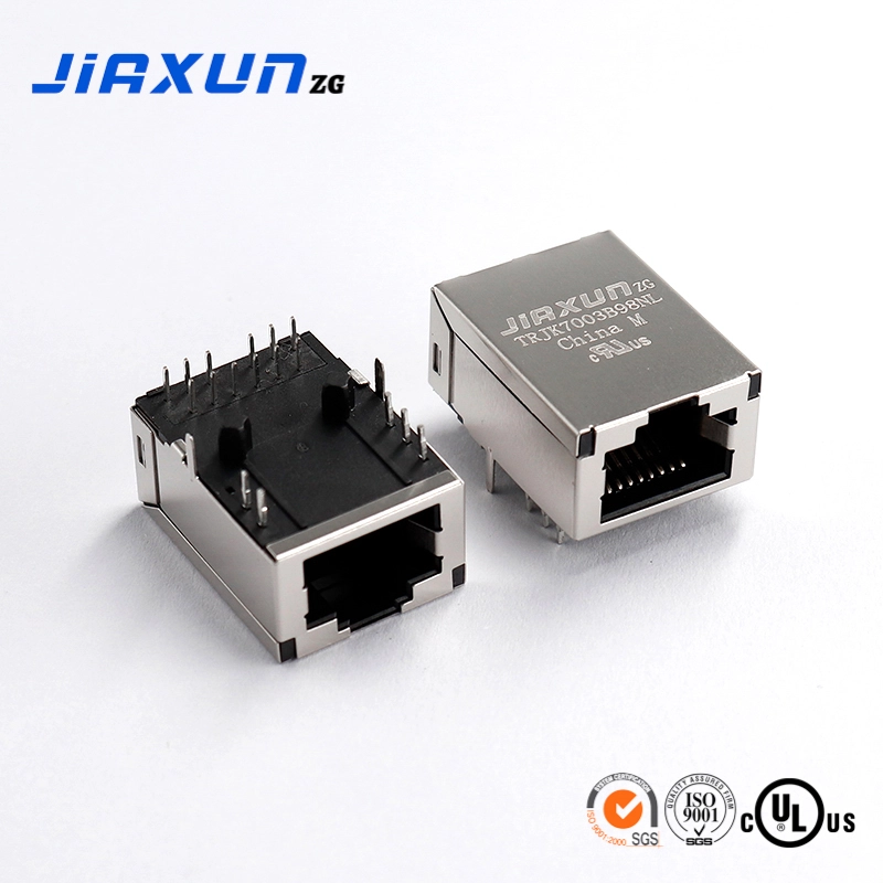
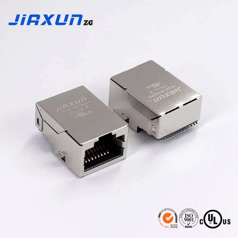
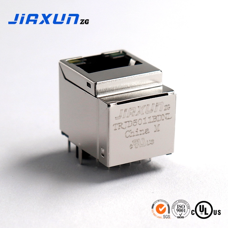
Against the backdrop of the accelerating penetration of in-vehicle Ethernet technology, Automotive Electronics RJ45 Interface As a key physical layer component connecting in-vehicle network nodes, its performance stability directly determines the reliability of core functions such as the intelligent cockpit and ADAS (Advanced Driver-Assistance Systems). Unlike consumer electronics scenarios, the automotive electronics environment faces harsh operating conditions—temperature cycles from -40℃ to 125℃, mechanical stress caused by continuous vibration, and complex electromagnetic interference generated by the ignition system, radar modules, etc. Therefore, when selecting, three core technical indicators should be focused on: waterproof performance (to cope with high-pressure cleaning, wading, and other humid environments), anti-interference ability (to meet automotive electromagnetic compatibility EMC standards), and transmission rate (to adapt to high-speed data transmission requirements). This article combines international standards and OEM test data to analyze the technical connotations and collaborative optimization strategies of the three indicators, providing engineers and procurement personnel with a scientific basis for selection.
Waterproof Performance: From IP Rating to Structural Design Technical Points
(1) Analysis of Waterproof Rating Standards for In-Vehicle Environments
Automotive electronics waterproof design follows the ISO 20653 international standard. In the core indicator IP rating, IP67 indicates that the interface can withstand immersion in 1 meter of water for 30 minutes without water ingress, suitable for relatively dry areas such as the driver's compartment and cockpit; while the IP68 rating can meet the needs of long-term underwater operation (such as high-pressure water gun washing in the engine compartment and wading scenarios in the chassis). The duration and depth of protection need to be customized according to the requirements of the car manufacturer (usually 2 meters of water immersion for 24 hours). Tests by a German car manufacturer show that IP66-rated interfaces that did not meet the standard had a 15% increase in water ingress failure rate after 20 high-pressure washes, indicating that the installation location (such as the engine compartment, chassis, and driver's compartment) is a key factor in determining the waterproof rating.
(2) Key Elements of Waterproof Design
- Selection of sealing materials: It is necessary to consider both temperature resistance and chemical stability. For engine compartment environments, fluororubber (FKM) sealing rings are recommended, and their oil corrosion resistance characteristics meet the requirements for long-term operation at 150℃; while chassis interfaces for vehicles in cold regions are more suitable for silicone rubber (VMQ), which can maintain elasticity at -50℃.
- Structural optimization design: A "dual-seal" scheme is adopted—the main sealing ring on the contact surface of the plug and socket is combined with a waterproof grommet at the end of the cable, doubly blocking the water seepage path. For example, the in-vehicle camera of a certain domestic electric vehicle Automotive Electronics RJ45 Connector reduces the risk of water ingress under vibration conditions by 60% through a snap-fit sealing ring and cable locking structure.
(3) Analysis of Typical Failure Cases
In after-sales feedback from a certain American model, it was found that Automotive Electronics RJ45 Network Interface because the rear waterproof treatment was not done, the reverse image screen flickered during the rainy season. Disassembly and inspection showed that due to long-term moisture erosion at the connection between the cable sheath and the interface, the metal contacts were oxidized, resulting in an increase in contact resistance, and ultimately causing signal interruption. This case increased the single-vehicle repair cost by 280 yuan and required a recall of 50,000 vehicles, highlighting the key role of waterproof design in overall vehicle reliability.
Anti-Interference Ability: EMC Design and Adaptability to the In-Vehicle Electromagnetic Environment
(1) Main Sources of In-Vehicle Electromagnetic Interference (EMI)
Electromagnetic interference in in-vehicle systems is divided into two categories: conducted interference and radiated interference. Conducted interference mainly comes from high-frequency noise (10kHz-1GHz band) generated by the engine IGBT module and motor controller, which is conducted to the interface through power lines and signal lines; radiated interference comes from radar, 5G T-BOX, and other wireless devices, forming spatial electromagnetic radiation in the 80MHz-6GHz band. Tests on a certain domestic brand model show that when the engine is running at full load, the signal bit error rate of interfaces without shielding treatment increased sharply from 10⁻¹³ to 10⁻⁸, seriously affecting ADAS data transmission.
(2) Anti-Interference Technical Solutions
- Hardware shielding design: Using a galvanized nickel alloy metal shell (shielding effectiveness ≥60dB@1GHz), the surface conductive oxidation treatment meets the IATF 16949 certification requirements, and combined with twisted-pair differential transmission (twist pitch ≤13mm), the common-mode interference suppression ratio can be improved by 40%.
- Grounding and filtering design: Multiple-point grounding of the interface shell and PCB board is achieved through metal springs (grounding impedance <50mΩ) to reduce ground loop interference; at the same time, the TDK BLM series common-mode choke is integrated, attenuating noise by more than 30dB in the 10MHz-100MHz band, and the insertion loss is controlled within 2dB, balancing anti-interference and transmission efficiency.
(3) EMC Test Standards and Certification
Products need to pass CISPR 25 Class 5 level testing, the core indicators include: radiated emission ≤40dBμV/m in the 30MHz-1GHz band, and conducted emission ≤70dBμV in the 150kHz-30MHz band. A Japanese supplier delayed the entire vehicle EMC certification by 3 months due to insufficient interface shielding effectiveness, indicating that anti-interference design is a necessary threshold for entering the OEM supply chain.
Transmission Rate: From Physical Layer Protocol to Signal Integrity Design
(1) In-Vehicle Ethernet Rate Standards and Application Scenarios
With the explosive growth of in-vehicle data volume (L2+ level vehicles have a single-lane data rate exceeding 2Gbps), Automotive Electronics RJ45 Interface multiple physical layer protocols need to be supported:
| Protocol Standard | Transmission Rate | Typical Application Scenarios | Cable Length Limit |
| 100BASE-T1 | 100Mbps | Body control, in-vehicle entertainment system | ≤15m |
| 1000BASE-T1 | 1Gbps | ADAS sensors, domain controller | ≤15m |
| 2.5GBASE-T1 | 2.5Gbps | 8-megapixel camera, LiDAR data transmission | ≤10m (planned) |
(II) Key parameters of signal integrity
- Return loss (RL): Requires ≤-20dB@100MHz. Interface terminal contact resistance (<50mΩ) and cable characteristic impedance (100±10Ω) must be controlled. A domestic connector uses gold-plated terminals to reduce contact resistance to 35mΩ, optimizing return loss by 15%.
- Delay skew: The delay difference between twisted pairs needs to be <5ns/m to avoid intersymbol interference (ISI) leading to bit error rate (BER) degradation. Tests show that at 1Gbps, for every 1ns/m increase in delay skew, BER increases from 10⁻¹² to 10⁻¹⁰, affecting the synchronization accuracy of ADAS sensor data.
(III) High-speed design challenges
High temperatures (>85℃) will cause changes in the dielectric constant of the cable. Polytetrafluoroethylene (PTFE) insulation material (dissipation factor <0.002) must be used. In densely installed scenarios, the distance between interfaces must be ≥2 times the cable outer diameter or metal baffles must be added to control crosstalk noise below -35dB, ensuring the data integrity of high-speed devices such as LiDAR.
Balanced strategy, selection decision model based on application scenarios
(I) Scene-based priority classification of requirements
The requirements for the three major indicators vary significantly depending on the installation location:
| Installation Location | Waterproof Requirements | Anti-interference Requirements | Rate Requirements | Typical Applications |
| Engine Compartment | ★★★★☆ | ★★★☆☆ | ★★☆☆☆ | ECU, engine sensors |
| Cockpit | ★★☆☆☆ | ★★★★☆ | ★★★★☆ | Central computing platform, intelligent cockpit |
| Chassis | ★★★★★ | ★★★☆☆ | ★★☆☆☆ | Wheel speed sensor, suspension control |
| Roof | ★★★☆☆ | ★★☆☆☆ | ★★★★★ | LiDAR, high-precision positioning antenna |
(II) Compromise scheme for technical parameters
- High waterproof scenarios (such as chassis sensors): Select IP68 rating Automotive Electronics RJ45 Connector and use a plastic shielding shell (cost reduction of 20%), supporting the 100BASE-T1 protocol. This balances cost and reliability while meeting the IPX9K high-pressure spray test.
- High-speed scenarios (such as domain controllers): Use IP67 metal shielded interfaces, integrate the NXP TJA1145 transformer module, support the 1000BASE-T1 protocol, and pass Class 5 EMC certification to meet the stringent signal integrity requirements of L3 autonomous driving.
- Cost-sensitive scenarios (such as body control modules): Use unshielded (UTP) interfaces and add LC filter circuits to the PCB end. This controls the cost per interface to less than 5 yuan while sacrificing 10% of anti-interference capability, suitable for low-speed body networks.
(III) Supplier selection suggestions
Prioritize suppliers with IATF 16949 certification: First-tier brands such as TE Connectivity and Molex offer customized waterproof solutions suitable for high-end models. Cost-effective options can consider Luxshare Precision and AVIC Optoelectronics, whose products have passed 1000-hour salt spray tests and 20G vibration tests and provide complete eye diagram test reports (signal rise time <0.5ns).
Conclusion: Systematic selection ensures the reliability of in-vehicle networks
Automotive Electronics RJ45 Interface Selection is not simply about finding the optimal solution for a single indicator, but a systematic decision-making process based on the installation environment, functional requirements, and cost budget. OEMs and parts companies need to build a three-dimensional evaluation system: First, clarify core scenario requirements (such as prioritizing speed and anti-interference for autonomous driving, and waterproofing for body control); second, verify the actual adaptability of the supplier's solution (requiring whole-vehicle EMC testing and high and low temperature cycle reports); and finally, reserve a 10%-20% performance margin (e.g., design the operating temperature at the highest expected temperature + 20℃). By scientifically balancing the three core indicators of waterproofing, anti-interference, and transmission rate, the risks of contact failure and signal distortion in the in-vehicle network can be effectively reduced, laying a solid foundation for the reliable architecture of intelligent vehicles.
Automotive electronics RJ45 interface,Automotive electronics RJ45 network interface,Automotive electronics RJ45 connector

19
2025-06
18
2025-06
18
2025-06
17
2025-06
17
2025-06
Industry 4.0 Essentials: Have You Chosen the Right RJ45 Connectors for Your Factory Automation?
17
2025-06
Data Center RJ45 Connectors: The "Core Hub" of Network Architecture
09
2025-06
Contact Us
Factory add: NO.54. Jinhu South Road, Chenjiang Town, Zhongkai Hi-tech Zone, Huicheng District, Huizhou city, China
Telephone:0752-2099791
Office add: B901-1, Silver Star Hi-Tech Building, No. 1301 Guanguang Road, Longhua District, Shenzhen, China
Website:www.jiaxunzg.cn
Telephone:0755-81752121
Fax: 0755-81752963
Mailbox:sales1@jiaxunzg.cn
Mailbox:sales2@jiaxunzg.cn
Mailbox:sales3@jiaxunzg.cn


Copyright © 2024 Jiaxun (Huizhou) Intelligent Technology Co., Ltd. Privacy Policy